PARTS LIST OF THE GEAR BOX

|
No.
|
NAME
|
No.
|
NAME
|
No.
|
NAME
|
No.
|
NAME
|
|
1
|
Box Body
|
13
|
Ratchet Wheel
|
25
|
Armor Plate
|
37
|
Taper Key
|
|
2
|
Pads
|
14
|
Dowels
|
26
|
Drive Bevel Gear
|
38
|
Shaft Sleeve
|
|
3
|
Bearing Block
|
15
|
Non-reverse Coupling
|
27
|
Oil Pipe Pack No.2
|
39
|
Glass Cover Pack
|
|
4
|
Paper Pad
|
16
|
Dust Cover
|
28
|
Vertical Shaft
|
40
|
Oil Cooler
|
|
5
|
End Cover
|
17
|
Abat-vent
|
29
|
Lower Bearing
|
|
|
|
6
|
Lip Type Seal
|
18
|
Dowels
|
30
|
Pump Pulley
|
|
|
|
7
|
Horizontal Shaft
|
19
|
Circinal Nut
|
31
|
Lining
|
|
|
|
8
|
Dexter Bearing
|
20
|
Dowels
|
32
|
Oil Ring Packing
|
|
|
|
9
|
Left Bearing
|
21
|
Flywheel
|
33
|
Base
|
|
|
|
10
|
Oil Pipe Pack No.1
|
22
|
Upper Cover
|
34
|
Paper Pad
|
|
|
|
11
|
Pads
|
23
|
Upper Bearing
|
35
|
Circinal Nut
|
|
|
|
12
|
Paper Pad
|
24
|
Driven Bevel Gear
|
36
|
Gasket
|
|
|
Appendices
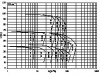
List 1 Downthrust Only
List 2 Speed Ratios
List 3 Transmission Parts Coupling Dimensions
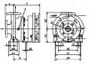
List 4 Boundary Dimensions
Drawing 1 Rotation Direction
Drawing 2 Boundary and coupling Dimensions
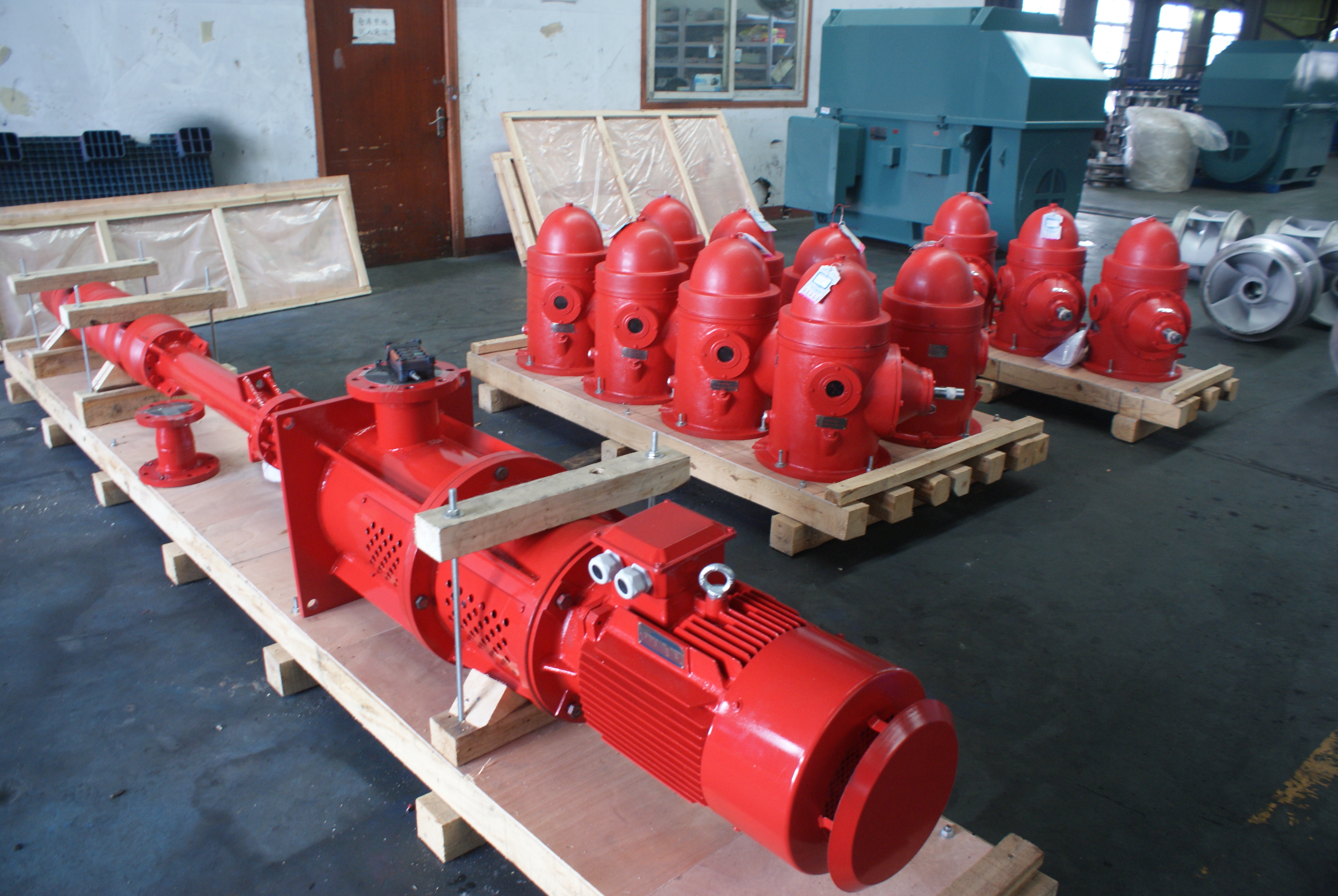
Series H Right Angle Gearboxes
Operating Instruction Manual
The horizontal shaft of series H right angle gearbox is direxct connected with a diesel, a horizontal type motor, a turbine, etc. Prime mover and after acceleration(or deceleration) the power is exported by the Vertical shaft. The series H right angle gearboxes are used for deep well pumps, axial pumps, inclined flow pumps, major axis pumps, sub-fluid pumps and other a variety of vertical shaft working machines to be driven and speed to be changed. They are used in a variety of fields such as: hydraulic engineering, municipal water supply and sewage disposal, smelter, mining area, petroleum and chemistry industry, fire protection and oceaneering, etc.. A variety of type and transmission ratios are available to meet specific requirements of high and low speed prime movers and working machines. Large capacity thrust bearings make the structure of working machine to be simplified. The series gearboxes have featuies of wide application range, economy, highly efficient, space-saving, and the ability to function well under varying climatic conditios.
In order to use well the series H gearboxes before operting please you have to read conscientiously the following all clauses, thanks!
1.Performance Parameters
1.1 The gears of the series H right angle gearbox are conical gear with curved teeth of Gleason tooth. the gears have large load carrying capacity and working smoothly, and is not sensitive to installation tolerance and deformation, but its axial thrust is larger and its rotation direction relate to direction of torque.
1.2 The gears are made with a steel 20CrMnTi. As the surface of cog-tooth is carburizing and quenching, the surface of tooth has higher hardness, whereas the core has better toughness.
1.3 The relations between the speed and power of gearbox output shaft, gearbox permitting the largest downthrust and necessary least downthrust are incorporated into the list 1. The axial thrust in the list are downthrust only. If requiring to withstand two-way thrust ――downthrust or upthrust you must raise when order or buy it.
1.4 Rotation direction: the horizontal shaft is clockwise seen from the stub end, and the vertical shaft is anticlockwise seen from above, see drawing 1. If requiring rotation direction is different from the drawing 1 you must raise when order or buy it
1.5 The speed ratios of the series H gearboxes amount to 19 kinds offering choice. The speed increasing ratios from 10:11 to 1:2 amount 7 kinds, and the speed decreasing ratios from 11:10 to 3:1 amount 11 kinds, and there is an isodromic ratio, see list 2.
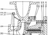
2.Main structure
2.1 As the vertical shaft of gearbox is hollow, the strength and rigidity of the shaft are raised, and the drive shaft of the working machine can be infixed in the hollow shaft to be mounted. The type 7000/DT duplex angular contact ball bearings are installed on the upper end of the vertical shaft, and they can bear larger downthrust only. The deep groove ball bearing is installed on the down end of the shaft,and it is a free end to bear a radial force only. The non-reverse coupling is also installed on the upper end of the shaft.
2.2 The spherical roller bearing is installed on the left end of the horizontal shaft, and it can bear a larger radial force and has certain self-aligning function. The left end bearing is a free end not to bear any axial force. The deep groove ball bearing is installed on the right end of the shaft, and it can bear an axial force which results from the gearing towards left or right besides a radial force.
2.3 The upper bearings of the vertical shaft are installed in an upper cover. The horizontal shaft and bearings are installed in a bearing block. Moving the upper cover and the bearing block you straight can adjust backlash and contact pattern of gear pair. There are paper pads between the upper cover or bearing block and a box body, and they act as sealing and adjusting.
2.4 The gear pair, bearings of horizontal shaft and upper bearings of vertical shaft adopt spraying oil for lubrication. The pressure oil are given by a pump puller of vertical shaft down end, and are carried to all oil site throught multipath pipeline. Besides the gears are lubricated by spraying oil of one pipeline, outflow lubricating oil from a distribution oil slot of the upper cover lubricate the upper bearings at one time lubricate the gears.
2.5 The gearboxes of type H60 and up externally mounted a cooler. After pressure oil cooled in the oil cooler, still flow into all spraying oil pipeline. Clean pressure water is connected to the oil cooler, and after flows through heat exchange pipes cooled for gear oil and the heat water issues from a return line.
3.Selection of Gearbox
3.1 According to shaft power and speed of the working machine a type of the gearbox is selected per the list 1. The list 1 set out speed range and corresponding power of all type of the serives H gearboxes. The power value in the list have contained a duty factor of 1.8 to 2.0, and may be direct selected, but shaft power of working machine not exceed the set value in the list.
3.2 According to speed of prime mover a speed ratio of gearbox is selected per the list 2.
3.3 Rotation direction of prime mover and working machine are checked, whether to agree with that of gearbox in the drawing 1. If you required that not agree with the drawing 1, while must specially explain when order.
3.4 The journal and keyseat of the drive shaft of working machine are checked whether to match with the aperture and keyseat of the non-reverse coupling of the gearbox. The aperture and keyseat of the input coupling are checked whether to match with the journal and keyseat of the horizontal shaft of the gearbox, See the list 3.
3.5 Checking the axial force, the down axial tensile force which working machine apply to gearbox must be greater than or equal to the minimum axial thrust and less than or equal to maximum in the list 1.
4.Installation of Gearbox
4.1 Work before installation
4.1.1 After opened box gearbox is cleaned and checked whether it is complete and damaged.
4.1.2 Stripping glass cover observe internal cleanness condition of the gearbox, and should wipe or rinse with diesel oil when it is necessary.
4.1.3 Inspect and screw down all tie bolts and lifting screws.
4.2 Connection of Gearbox and Working machine
4.2.1 Inspect each fitting size of the gearbox whether to match with correlative size of the working machine following: the aperture and keyseat of the non-reverse coupling i.e. size “BZ”, “XD”, “XL”, “Y”, and “BZ” in the drawing 2 and the list 3; the rabbet and the bolthole of the box body i.e. size “AK”, “BB”, “AJ” and “BF” in the drawing 2 and the list 4.
4.2.2 Hoist on the gearbox to foundation in the meantime the drive shaft of working machine is past through the hollow shaft of gearbox, and tie bolts of gearbox and the foundation are set and screw up the nuts.
4.2.3 Set the gib head taper stock key. Screw up the nut of drive shaft end and the lock bolt.
4.2.4 It is inspected that the gearbox drives the working machine rotating whether to be normal, and screw down the tie nuts of gearbox and the foundation next.
4.3 Connection of Gearbox and Prime Mover
4.3.1 It is inspected whether the center-height of the prime mover are the same with the horizontal shaft center-height of the gearbox i.e. size “D” in the drawing 2 and the list 4. It is inspected whether the aperture and keyseat of the input coupling are in agreement with the correlative size of the gearbox horizontal i.e. size “U”, “N” and “X” in the drawing 2 and the list 3.
4.3.2 The horizontal shaft of gearbox is direct connected to the output shaft of the prime mover by means of the input coupling and a straight key. The axiality of two shafts is inspected and adjusted, and the specific value is decided on to base magnitude of the ability which the coupling compensate for defection of two shafts.
4.3.3 Screw down the tie bolts of the prime mover and the base frame and one of the input coupling. Inspect the set turning whether to be normal.
4.4 Installation of Accessories
4.4.1 Dust cover of the gearbox is installed.
4.4.2 For type H60 and up gearbox must joins a feed pipe and a return pipe to the oil cooler, and the joint adapter is a taper-pipe-thread Rc1/2. The feedwater pressure is from 0.15 to 0.3 MPa, and the temperature is about 20℃.
4.4.3 A safety cover of the input coupling is installed(consumer autonomous).
4.5 Adding Clean Gear Oil of Qualification
This gearbox uses type L-CKC 68 of medium load industry gear oil(GB5903-1995),and its kinematic viscosity is from 60 to 75mm2/s(centistokes) at the temperature to be 40℃. If the ambient temperature is generally greater than 30℃ you must choose a gear oil whose kinematic viscosity is greater. When the temperature rises per 10℃ the viscosity rises correspondingly for 10%. If it is less than 10℃ you may choose one whose viscosity is less. When it sinks per 3℃ the viscosity may correspondingly sink for 10%. Every tim oiling, the oil level must be flush with the thread bottom of the filler.
5.Use of Gearbox
5.1 The rotation direction of the prime mover must correspong with the stipulation of the drawing 1, otherwise the gears will be not turned and the machine can be caused owing to the stopping effect of the non-reverse coupling. If the prime mover is a electromotor after shutdown the rotation direction must be inspected whether to be changed before starting next time.
5.2 The output power of the prime mover shall be less than or equal to the corresponding power value of the list 1. Diverse type of the gearbox allow speed of vertical shaft to be diverse, when you use , please don’t exceed assigned to maximum speed in the list 1. The input speed of the gearbox don’t exceed 3,650 rpm, see the speed decreasing ratios column in list 2.
5.3 In running the downward tenside force that the working machine acts on the vertical shaft of gearbox isn’t below the minimum axial thrust in the list 1, otherwise an axial force of the gearbox and appending an axial force by the upper bearing will make the inner race of bearing separating upward by the vertical shaft carrying, so that affects normal motion of the bearings and the gear pair even causes the gears, bearings and shafts, etc. parts to be destruction. The downward tenside force neither can be greater than the maximum axial thrust in the list 1, otherwise the working life of the upper bearings will be reduced.
5.4 For the first time have given gearbox to have added oil or having replaced oil, after working one number of runs should take apart the plug screw of the filler, and inspect the oil level of the gearbox before starting at second number of runs. When the oil level is below the thread bottom of the filler, should supplement oiling. In the context of the gearbox does not leak afterwards the oil level have been inspected once per week. To discover leaking you must find the cause and remove the fault promply.
5.5 During gearbox running you must survey on time the case that the lubricating oil are sprayed. If insrfficient quantity of spraying oil, ought to be a shutdown inspection when make that spraying oil are restored to normal only can go on use. During running yet note vibration, sound and temperature of the gearbox whether to be normal.
6.Maintenance of Gearbox
6.1 It is the first time that New gearbox has bee used, after running for 300 hours you must renew the gear oil. After shutdown the oil which is hot is discharged at once. After during running each 2,000 hrs. of running or amounted to 6 months of natural time taking first achievement of them the gear oil should be renewed usually.
6.2 All bolts are inspected and screwed down regularly.
6.3 Usually when gearbox has run to 6,000 hrs. after the gear oil is discharged, diesel oil is added to the oil level of the stipulation, and the prime mover is used driving gearbox free running for one minute. After the diesel oil hasing been discharged backlash and contact pattern of the gear pair are inspected, and are adjusted if necessary. The adjusting method see clause 2.3 and the specific data see “Technical Requirments” in assembly drawing of gearbox supplied with machine. Afler to have finiched adjusting new gear oil are added.
6.4 After the gearbox working 20,000 hrs. the clearance and wear conditions should be inspected for two end bearings of the horizontal shaft and upper bearings of the vertical shaft, and at exceeding limit should be renewed. Attention: new bearing ought to be heated in lubricant first, before is set to shaft. The down bearing of the vertical shaft isn’t liable to dismount owing to its down end there is a pump pulley whose shrink range is much, so the working life of the bearing has been designed to be very long. Under conditions that the gearbox uses and lubricates normally its working life is generally from 70,000 to 100,000 hours. |